- measure the FWHM and FSR of the etalon.
- additional result is the gap value, if the index of the cavity is known.
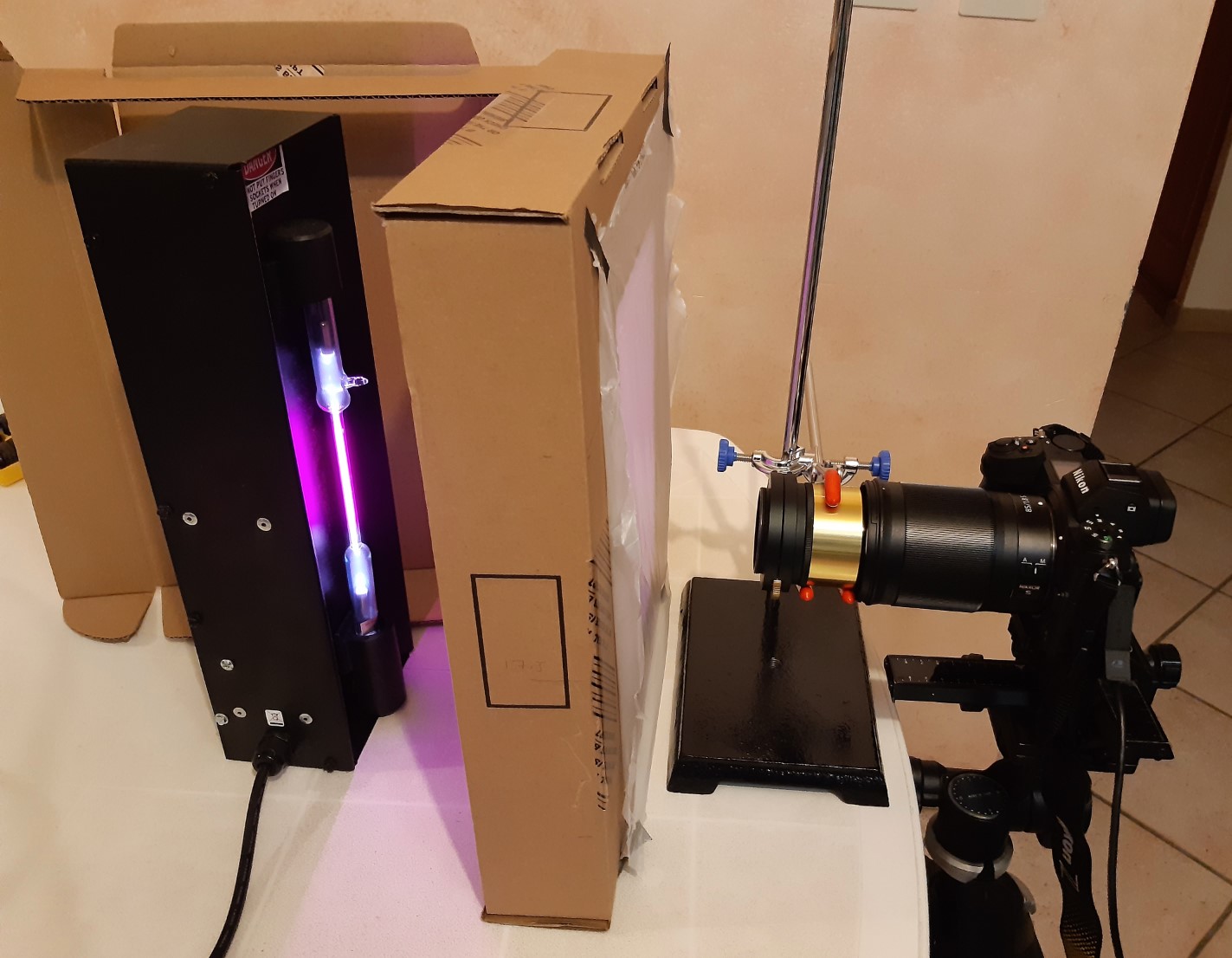
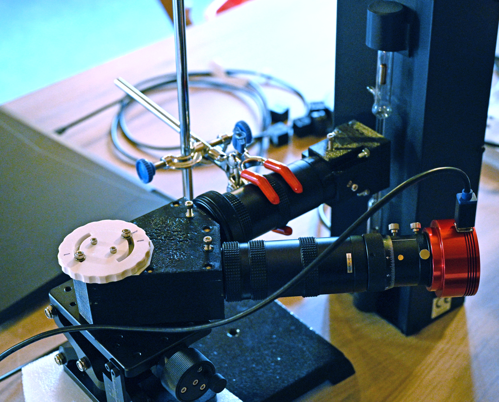
2) Optical setup (front left to right) :
- an hydrogen discharge lamp is used as the light source (from Edmund Optics) ;
- a diffuser is placed 20 cm away from the lamp ;
- the etalon is placed next to the diffuser ;
- a camera with its lens focussed at the infinite takes the image of the interference pattern.
3) Principle of the test:
The etalon is used as a Fabry-Perot interferometer. A system of cicular fringes is observed when looking through the etalon or with a camera whose lens is focused at infinite.
The wavelength is given by the lamp (Ha = 6562.8 A, the other lines of hydrogen are very faint, and can be blocked with a red filter).
Thus the transmission profile is a function of the angle i of the incident light. For a reminder, when used as a Fabry-Perot etalon, the transmission curve is a function of the wavelenght of the incident light.
4) Measuring procedure and calculation of the FWHM and FSR:
François Rouvière (contributor to Solar Astronomy book) established the formulae for deriving the FSR and the FWHM of the etalon from the measurement (positions and FWHM) of the fringe interference pattern. A big thanks for this !
5) Qualitative interpretation of the fringe pattern:
Even if not you are interested not in making actual measurements and calculations, some qualitative information about the etalon can be derived from visual inspection of the fringe pattern.
(a) Qualitative information on the CWL
The test takes advantage of the following observations:
- when the CWL of the etalon at normal incidence is precisely exactly on the Ha line, the central fringe reduces into a central spot,
- if there is a small CWL offset, a small central dip appears in the central spot,
- as the CWL offset increases, the central fringe evolves into a ring whose diameter increases with the CWL offset.
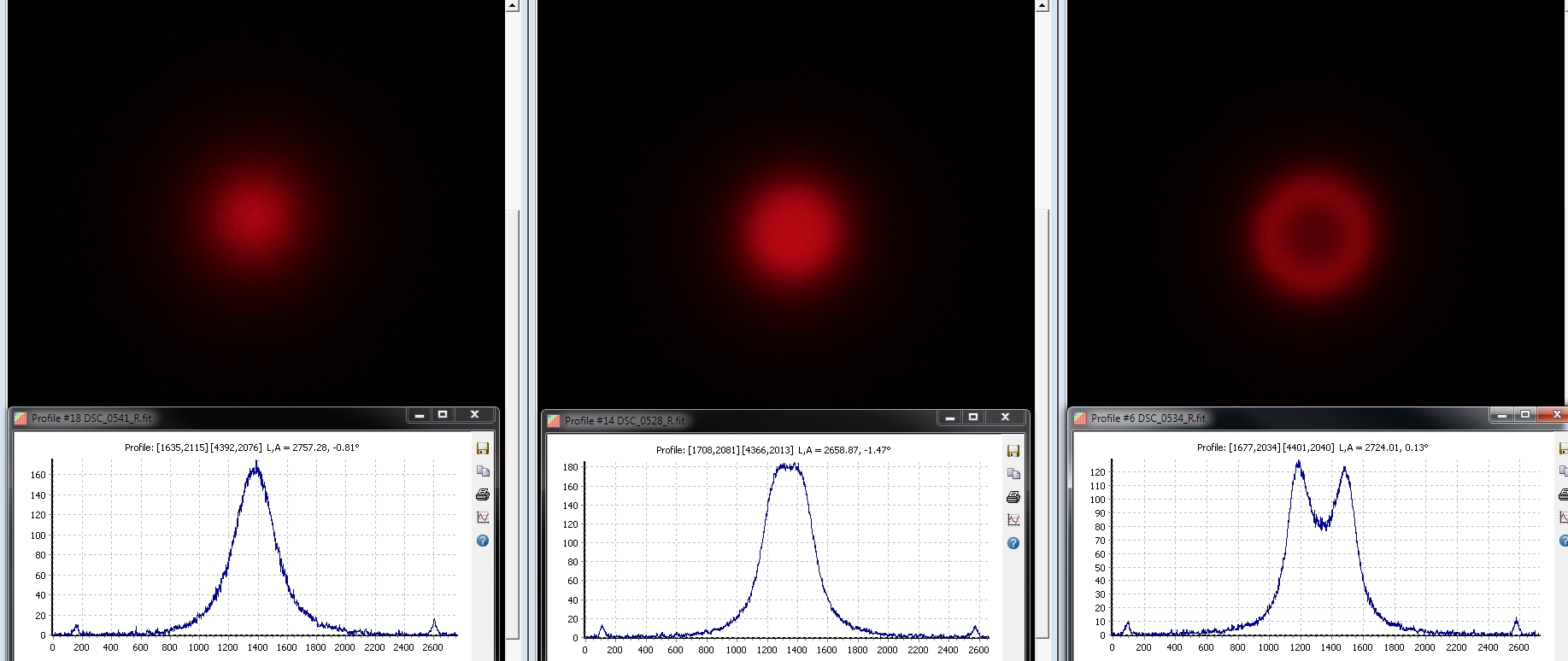
Central interference pattern observed through a thermo-regulated mica-spaced etalon at three different settinngs of wavelengths : Ha, Ha +0.5A, Ha + 1.0 A. At +0.5A, the top of the central peak flattens. At Ha + 1.0 A, it turns into a small ring.
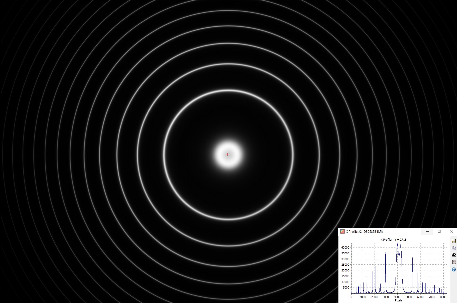
Lunt LS40FHa (air-spaced etalon) - Interference fringe pattern - Nikon Z7II - 85 mm S f/1.8 Nikkor lens at f/2.0 (i.e. 40 mm aperture) - 12-bit RAW file - 0.25 s - 100 ISO - 17 January 2025
The offset from Ha is +0.21 A (=blue shifted)
(b) Qualitative information on the CWL uniformity
As the eye (or the camera) is moved laterally along a diameter of the aperture, the eye (or the camera) samples different areas of the etalon. The area of the sampled region is determined by the size of the eye pupil (or by the aperture stop of the camera). If the CWL is uniform across the surface of the etalon, the central fringe pattern (spot or ring) remains unchanged. Any change in the central fringe pattern indicates a nonuniformity of the CWL along the diameter sampled.
This test of the uniformity of the CWL is qualitative but quite sensitive and relevant.
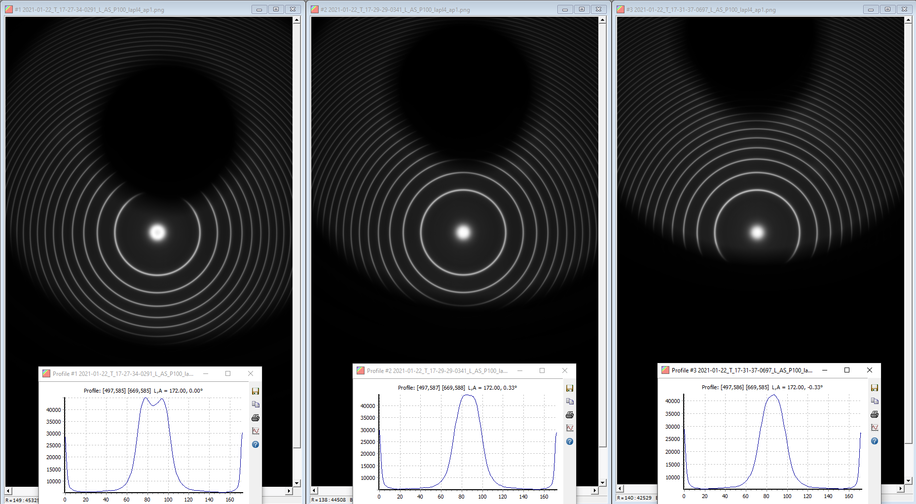
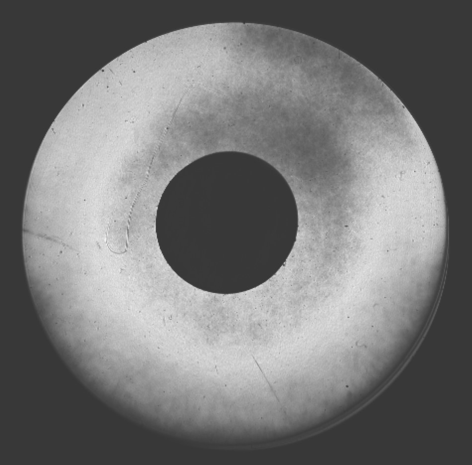
The top circular shadow is the obstruction by the central spacer. A 3.3 mm aperture was used to sample the etalon.
A small variation of the CWL is observed. It appears as a small dip in the tranmission profile (left).
(c) Qualitative information on the FWHM
It is not possible to obtain quantitative information on the FWHM by visual inspection, except by comparison with a reference (i.e., previously measured) etalon.
However, the width of the fringes is related to the finesse of the etalon. The larger the finesse, the thinner the fringes.
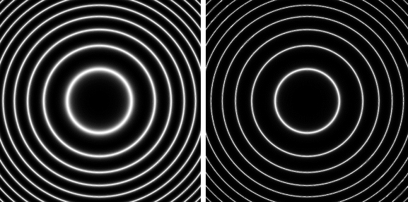
Simulations made with webmatematica (multiple beam interference) - https://wp.optics.arizona.edu/jcwyant/mathematica/webmathematica/
- The test is only qualitative (at this stage). It examines transmission variations across the etalon aperture. These variations result from local variations in peak transmission, CWL and to a lesser extent FWHM across the surface of the etalon. Indeed, if the CWL is exactly on the Ha line, any FWHM nonuniformity will have no effect on the resulting image.
- For mica-spaced etalons, the transmission variations can be due to default in mica cleavage, striae, inclusions or refractive index inhomogeneities. For air-spaced etalon, transmission variations can result from thickness variation in the air gap, roughness, polishing defects, non unifom coating.
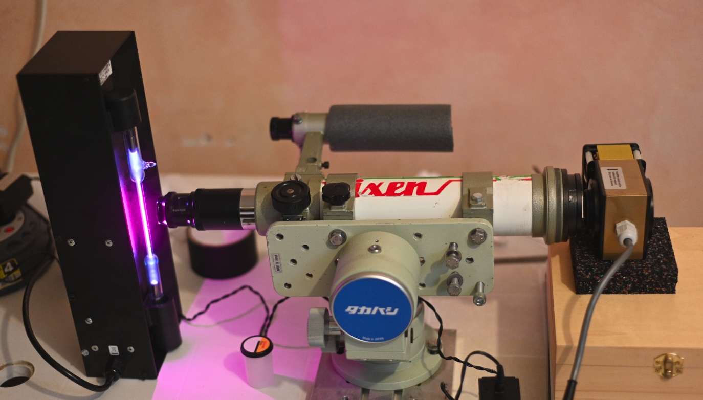
Optical setup (front left to right) :
- a hydrogen discharge lamp is used as the light source ;
- a 55 mm f/8 refractor is used as a collimator to illuminate the entire surface of the etalon. A 5 mm (or smaller) aperture stop placed next to the lamp limits the angular aperture of the light source to 1:88 (= 5 mm/440 mm) or 0.65°. Accordingly, the most oblique beam (0.32°) introduces a CWL shift of 0.1 Å for air-spaced etalon and 0.04 Å for mica-spaced etalon, which is quite acceptable ;
- the etalon is placed in front of the refractor lens and square to its optical axis ;
- the image of the etalon is taken by a camera (not shown in the figure) placed about 50 cm in front of the etalon. The focus of the camera is set on the etalon surface (which is a bit difficult to achieve ...).
Note : As the light beam is collimated, the aperture of the camera lens determines the area of etalon sampled. For example, a 50 mm focal length f/1/8 lens samples a 28 mm diameter area. This is usually large enough for mica-spaced etalons, but small compared to the free aperture of air-spaced etalons.
The test is very sensitive to non uniformities. Here are two mica-spaced etalons which look terrible in these images, but still show excellent uniformity at the telescope.
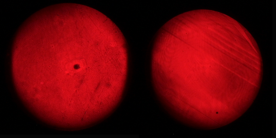
Nikon Z6 camera - 50 mm f/1.8 Nikkor lens.
Coronado SM 40 - Nikon Z6 camera - 85 mm f/1.8 S Nikkor lens - 14-bit RAW file - Red channel - 1/30 s exposure - 100 ISO.
FWHM of the hydrogen Ha lamp
The profile of the Ha line was measured with different configurations of the Sol'Ex spectrometer (10 micron slit, fc= 80 mm, 125 mm or 200 mm, fi=125 mm or 200 mm, 2400 l/mm grating, 2.9 micron pixel size).
Measurement made at hightest spectral resolution gives FHWM = 0.263 A.
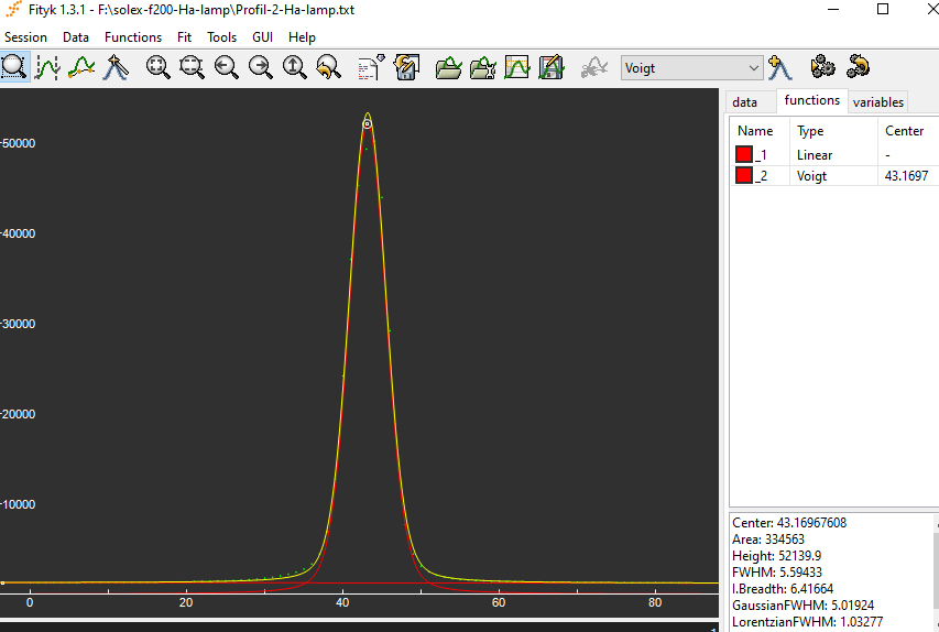
Measurement of the FWHM of the hydrogen lamp (at Ha) with the spectrometer ( 10 micron slit, fc=fi=200 mm, 2400 l/mm, 2.9 micron pixel size).
Curve fiting with Voigt function .
../Solex/Solex.html