Comparison of air-spaced (PST modification) and mica-spaced F-P etalons
Daystar filter modelling and additional results
Air-spaced F-P etalon theoritical performances and comparison with mica-spaced etalons
Tilted air-spaced etalons in telecentric beam or in a f/115 convergent beam
Analysis of the PST modification (air-spaced F-P etalon) and comparison between collimated and telecentric mounts
Contrast factor of the F-P etalon and blocking filter assembly
Contrast factor of the F-P etalon : test of various stacking schemes
Fabry-Perot math and bibliography
Comparison of PST etalon in a collimated beam (refered here as "PST modification") or a telecentric beam.
|
|
|
|
|
|
| Uniformity of CWL and FWHM |
|
|
|
| Peak transmission and use in double-stack configuration | Because of the filter stack (in
particular the use of two polarizers), mica-spaced etalons have much
lower peak transmission (between 2 to 10%) than air-spaced etalons
(about 70-80%). Mica-spaced etalons with high peak transmission can be double-stacked with air-spaced etalons (but not with another mica-spaced etalon). Double-stacked air-spaced etalon have much greater peak transmission than mica-spaced + air-spaced combinations. |
| Optical set-up | Air-spaced etalon are usually mounted in collimated beam : - Accordingly, the FWHM at the center of the field is equal to the nominal FWHM. This is the main reason why air-spaced etalon are often reported as more selective. - On the other hand, the FWHM increases with field angle, resulting in a sweet spot effect. Mica-spaced etalon are usually mounted in a telecentric beam : - Accordingly, the FWHM at the center of the field is larger than the nominal FWHM. This is the main reason why air-spaced etalon are often reported as more selective. - On the other hand, the FWHM does not change with field angle (no sweet spot effect). In a telecentric beam, the f-ratio should be large enough to avoid a too large broadening of the FWHM (> f/30 for mica-spaced etalons, > f/45 for air-spaced etalons) |
We assumed the following data for the PST :
- a 20 mm diameter air-spaced F-P etalon with FWHM = 1 A,
- front divergent lens of -200 mm focal length (ie f/d = 10).
Requirements on the optical path :
xxxxxxxxxxxGraph to be placed here xxxxxxxxxxxxxxxxx
with :
F : focal lens of the refractor
D : diameter of the refractor
(i) The focus of the refractor should be set at the rear focus of the Barlow lens. In other words, the PST Barlow + F-P assembly should be placed 200 mm before the focus of the refractor. This turns the incoming convergent beam formed by the objective of the refractor into a collimated beam (with field angle). This is true whatever the F/D ratio of the objective of the refractor.
(ii) The F-P etalon receiving a collimated beam with a field angle, there is a shift of the CWL, but no FWHM broadnening.
(iii) The field angle at the F-P etalon is equal to the incoming angle multiplied by F / f (see graph).
(iv) Because the divergent lens in front of the etalon has a f/d = 10 ratio, the objective of the refractor is vignated to F/10. In other words, a 100 mm F/8 objective would have an effective diameter of 80 mm. Accordingly, this set up is to be used with objectives having F/D > 10.
(v) On the other hand, for a given theoritical resolution of the refractor (ie. for a given diameter D), the sweet spot increases with smaller field angle, ie. lower F / f ratio, or shorter focal lens F, or smaller F/D.
(vi) From (iv) and (v), we can conclude that the optimal balance between the largest theoritical resolution and the largest sweet spot is reached when F/D = 10.
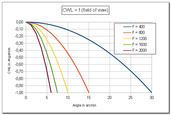
CWL shift in function of objective focal length :
The following figure shows the drop in the diameter of the sweet spot when the focal length of the refractor increases :
The "native PST" with its 400 mm focal length has a 0.25 A CWL shift for a 15 arcmin angle (radius of the sun). This is why it covers the full solar disk in Ha.
Sweet spot radius :
This figure is another way to present the previous results :
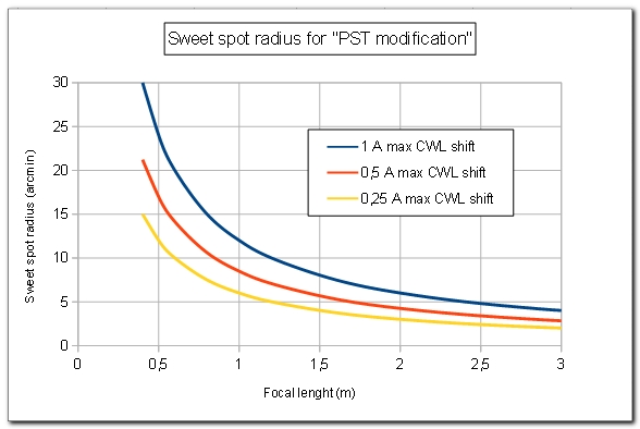
If is remember that the focal lenght F indicated in this figure is the native focal length of the refractor. The resulting focal length of the combined system can be increased by adding a Barlow lens after the F-P etalon.
The conclusion is that we should keep the native focal length of the refractor as short as possible in order to cover the largest possible sweet spot for a given diameter D. In other words, the optimal F/D ratio is 10.
How to increase the radius of the sweet spot ?
Given that the field angle increases with the factor F/f, one solution to have a larger sweet spot would be replace the -200 mm FL divergent lens of the PST etalon by a divergent lens of longer focal length (eg. -400 mm or longer).
Here we only keep the air-spaced etalon of the PST without its divergent and convergent lenses. The F-P is placed behind a telecentric lens system.
We have already seen this figure. It shows that air-spaced F-P etalons require much larger f-ratio.
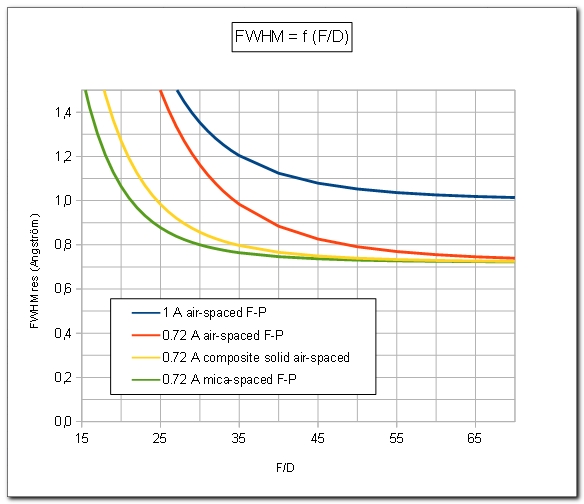
The results are even worse if we suppose the PST F-P etalon is indeed 1 A FWHM. However, the PST etalons show a lot of variability. The author measured one PST etalon at 0.35 A FWHM